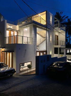
Elegant House Design at Pannipitiya

 This elegant house's architectural design is done by the architect, Chathura Perera. His designs have unique features but arranged in a simple grid system which leads for economical beam designs. If the house or building has simple square based continuous grid system it will be able to used parallel continuous equal span beams and they usually have smaller beam depths and minimum reinforcement areas which leads to lower the material and construction costs. Actually architecture is not a word for unique building elements which used a very difficult construction methods with a higher cost. It is a science of having the required utilities with a minimum cost and contains an elegant appearance. This thing is nicely handled by Architect Chathura Perera and Hats off for him and his designs. 
The house is constructed near pannipitiya and very close to Devram Viharaya. The Structural design is done by Chartered Structural Engineer, Isuru S. Amarasena. He is working as a Senior Design Engineer (Structural) in the Structural design section of Central Engineering Consultancy Bureau. 

The substructure is having some pad foundations with 3ftx3ft and 3.5ftx3.5ft sizes. All the foundations are connected with tie beams. The loose soil part was found during the excavation of foundations and it was filled and compacted with quarry dust for a better bearing capacity and to avoid the differential settlements. 
This unique project is now almost completed and very few small small things are remaining. See It has an elegant look at night for lights. Thanks to the experienced contractor who didn't ruin the design and gave the nice finish and same sight as in the 3d modal. 


House of an Electrical Engineer in Hokandara

This two story housing unit was proposed to build in Hokandara area near Colombo. The Architectural Design was done by Mr:Chathura Perera. The total land area is 9.8 Perches and the total floor area of the house is 3060 square feet. The ground floor is consisted with a single car parking slot and the side road with the dead end could be used for additional ceremonial parking. 
In the ground floor 1 bed room with attached bathroom, living room,  kitchen, servant's room and toilet are placed. The Architect has taken successful effort to have a more spacious look inside the house. So in the first floor he has designed like two reinforced concrete slab parts connected to each other by a small narrow timber deck which is supported on two Steel "I" beams. In the either sides of that small bridge type arrangement double height spaces were placed. In the first floor master bed room is placed with the nice look of the paddy fields through the side road. another two bed rooms are placed in the rear side of the house with a common bathroom.
    the top slab of the parking area has used as the first floor open terrace to the sky with a flower trough. The second floor terrace is used as the larger ceremonial open terrace area. Another third slab is placed to cover the stairs and it is proposed to utilize as the water tank slab.
        
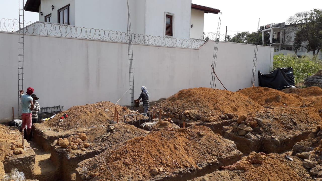
    The structural design is done by Chartered Structural Engineer, Isuru S. Amarasena. He has visited the site initially and looked at the side conditions and the soil conditions. As a hard type kabok soil strata was identified through out the land under 2 feet from the existing soil 3x3, 3.5x3.5  sized pad footings could be used for the substructure. In order to compliance with the Robustness Criteria, 9x9 tie beams were prosed with T12 Diameter reinforcement bars with R6 stirrups at 125mm interval spacing. Rubble foundation with different sizes were proposed for different areas of the house according to the considerable level differences. One blind wall (Blind end) is faced to a existing boundary wall with a longer height of the neighboring land and special attention was given for that side. Separation of two structures and water tightness were taken in to account when designing them. In order to avoid the strap footings which needed a high attention and a high cost, the columns at the blind end are shifted towards the house inside the walls. So no, eccentric footings were used for the constructions. Below are few images taken during the foundation construction stage. 


Here you can see the pad foundation base pits with their reinforcement nets. The soil excavation is done in an effective way considering the required depths for the rubble wall foundation depths and tie beams. 
This image is taken after placing the rubble foundations. The column reinforcement has come out of the pad bases. 


2 Story House at Bataduwa, Galle

After the construction works done, the house's front view image is attached below. 
During the constructions very few slight modifications has been done. This photo was taken before the landscaping work.

 
The site was situated in the down south of Sri Lanka, very close to the Galle town area. The place had an old single floor housing unit and the same area was utilized for the new house, after demolishing the old one.


A different type of weak soil layer was found near to the rear end of the building and as well as near an old toilet pit. The base pits were excavated to a certain depth by looking for a stable soil and as an additional safety precaution concrete rings (Cylinders) were used and inside the ring a compacted quarry dust layer was used. With this process it is believed that the differential settlements were tolerated if any. 


Around 20  umbers of columns and column bases were used for the housing project and three floating columns were used for maintaining the architectural requirements as it is. 


These images show some steps during the structural modal analysis. 
The first one shows the axial forces acted on columns. But it is not the only governing factor of reinforcement for columns. The bending moment also should be considered.


Below two images denote the slab stresses.


Below image shows the deflected shape of the building due to the loadings. You can clearly see the deformed beams and columns here. In order to withstand straight in the application of loads we have to provide the steel requirements in those places. But providing the same reinforcement area for the entire element doesn't give an economical design. So design optimization should be taken in to account in house designing. 


After the construction Stage, The final outcome can be Seen here below.


3 Story house at Rathnayake Mawatha, Pelawatta.

An Elegant Architectural design by Chartered Architect Amila Ruwan Liyanapathirana for a calm and quite inside road at the busy premises of Pelawatta, Battaramulla. 
3 Floor housing unit has designed with maximizing the open spaces such as balconies and lobbies. The design has  atwo unit car parking area next to a ramping floor in order to maintain the level differences with the road. Living and dining are connected together with a larger area and also connected visually wth the swimming pool in the garden via glass facades. Two small storage rooms are provided for motor equipment storing and also for general purpose storing next to car park. In the ground floor Kitchen  is located next to dining together with the dirty kitchen in outside. Servant's room is also attached next to the dirty kitchen area. An outside toilet and a common toilet facility is provided in the ground floor. 


Remada Building at Kotikawatta (6 Story)


\

This unique 5 Story building is designed in a very urbanized area of Kotikawaththa town. It is faced to Low level main road which goes from Colombo to Awissawella. Basement is designed for car parking areas and the Ground floor and first floor are designed for commercial purpose. Rest two floors are for accommodation purposes. 

The superstructure is designed on Pad foundations as the soil condition is good. All the foundations were tied in dpc level in order to build a robhust structure as it provides horizontal ties in the building in below levels. In one side small retaining wall part was needed to built as there was a level difference between the side road and the basement floor level. The lift pit was constructed by the reinforced concrete and the above lift walls were supposed to build by using the block work. Perimeter wall loads were taken in to load calculations and for interior walls partition boards were used in order to reduce the dead weights on beams. Actually it lead design in to an economical one. 

Structural Review of a Commercial Building near Biyagama Free Trade Zone

     This commercial building was proposed to design with 3 reinforced concrete slabs and structural design has not done earlier. The masons and the client together have planned the construction works and first floor slab was casted. The ground floor part and the first slab soffit was finished and they were about to start a food city type shop in the ground floor area. At that time they have noticed several cracks formed under several beams and they have propagated further.
    In that stage client requested to visit the site and he request a remedial measure advice for the issue. Chartered Engineer Isuru S. Amarasena visited the site and took the measurements of the cracks and observed the nature of the cracks. According to the available information amount and types and lengths of the reinforcement  used were noted down. 
    Then he did a structural analysis using a structural design & modelling software and came to know that the adequate reinforcement has provided to the sections (If only their information is correct). Then he believed that should be an issue with the construction material used or the construction method or quality controlling. However according to the available budget frame, further core tests or any quality checking test were avoided by the client. 
    Then he inquired about the further propagation of cracks and after a duration noticed that the propagation has stopped and cracks are still. So he recommended a repairing the cracks using a special non shrinkage grout. 
Below shown is a image of the structural modal used by the structural engineer for the analysis.

A 2 story House included with an adorable bridge in Awissawella, Sri Lanka.

    This awesome house is constructed in Avissawella, is a township in Sri Lanka, governed by an Urban Council, situated on the A4 route from Colombo to Ratnapura, Colombo District, Western Province, Sri Lanka, approximately 59 km east of capital Colombo. The awsome architectural design is done by the Chartered Architect: Jagath Jeewantha. Structural design was done by Chartered Structural Engineer, Isuru S. Amarasena. 
     Previously built old house was situated here and it was demolished and the debries were removed from the site initially. In ones side an embankment was there with a height of 6-8 feet. A reinforced concrete wall was proposed for that side with the appropriate waterproofing system. A small basement part was inside the design by utilizing the available ground levels. For that place a Retaining wall was proposed and designed with waterproofing as it was utilized as a room. 
    Although this house is a single unit, it was separated as 2 units and interconnected by an adorable bridge. Bridge was designed as a one-way spanning reinforced concrete slab. The foundations were connected with RC Tie beams on the rubble wall parts. But the client was so significant about the avoiding cross tie beams according  to the astrological advice. So the two foundation units were not interconnected by tie beams. But the slab itself connected the two units. As similar loading were available in the two units, differential settlement was not expected here. If a crack formed, it should have to be repaired after inspecting the termination of the settlements.

    All the foundations were Pad foundations and 4'x4', 3.5'x3.5' and 3'x3' sizes were used in different places. 9"x9" RC columns were used everywhere. Slab thicknesses were 5" except few places. T10 reinforcement bars in 9" spacing were used for the slab reinforcements. 
    This unique design is now about be completed and then it will become an amazing living space.

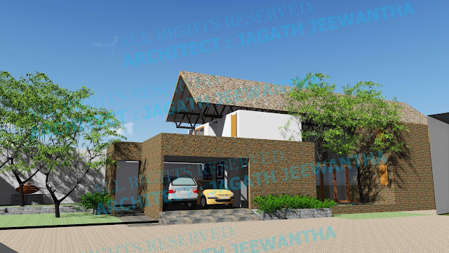
Shown below is a photo of the architectural modal done by the Architect.

Below shown is a photo of the structural Modal done by the Structural Engineer.
Below shown are the Axial forces on each column of the building taken during the structural design.


Below photo is taken during the construction of the first floor slab.

Columns are lifted as two concrete pours and connected with barraemulsion.
These are few from Structural Drawings.

Retaining wall for basement room with waterproofing.

This is how it looked like, before start constructions. The debris are from the previous house which was demolished just before the construction started. 


Accident & Emergency Unit (4 Story) Building - General Hospital, Kaluthara

Kalutara General Hospital is next to Nagoda and is located in Western, Sri Lanka. Proposed project Site was located within the present premi...